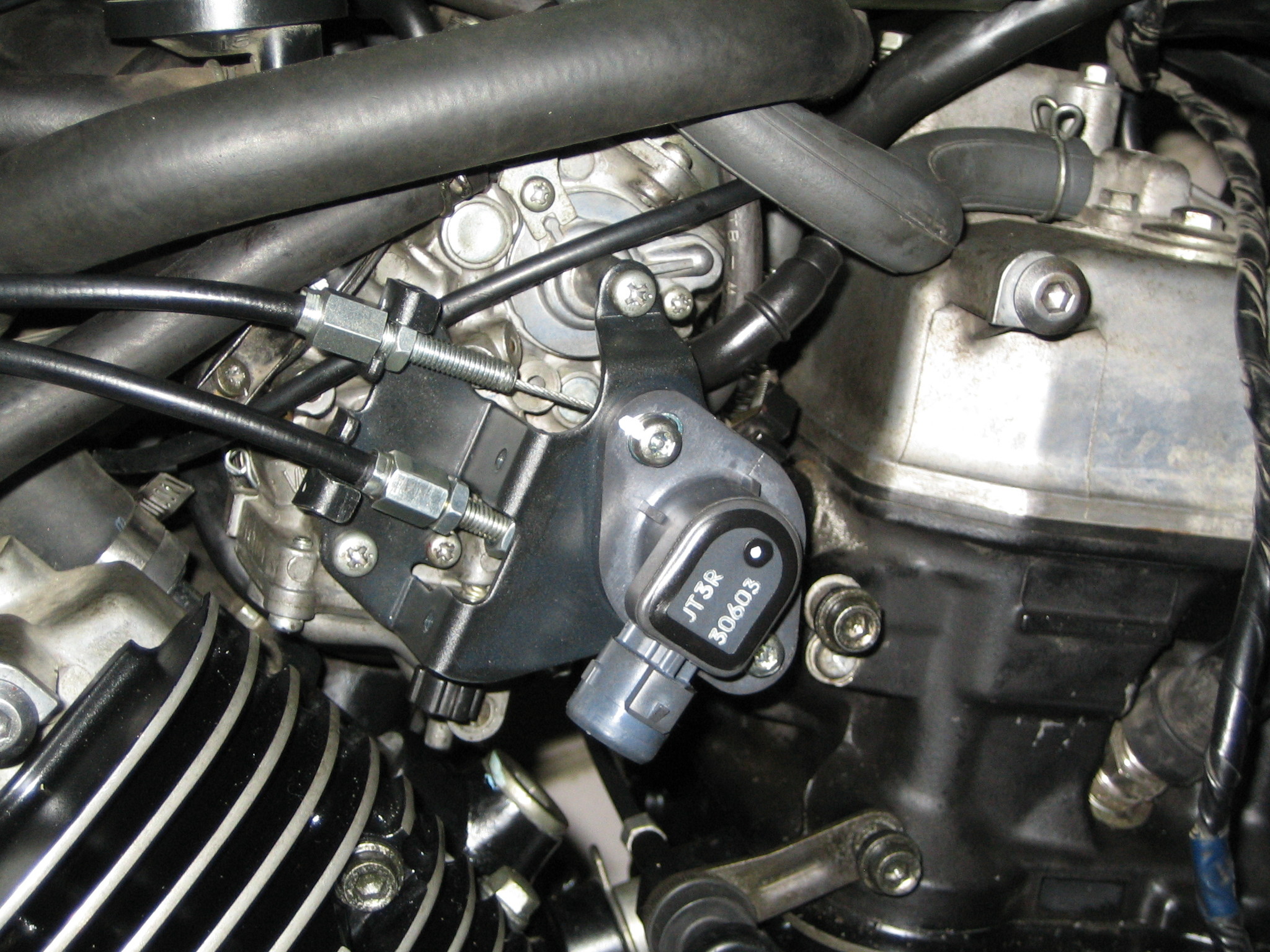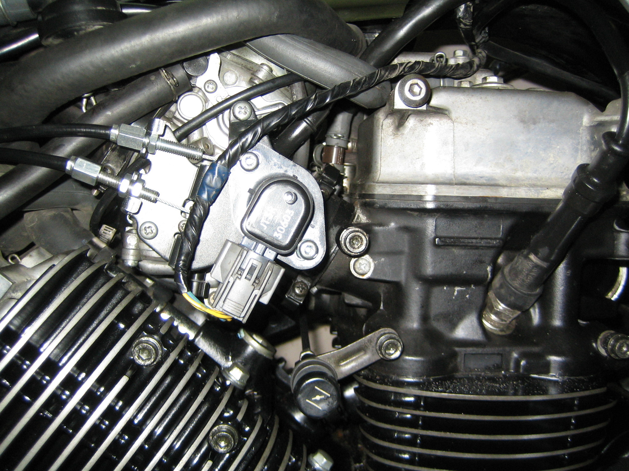
Датчик положения дрос. заслонки
#1
 Отправлено 07 ноября 2013 - 05:23

#2
 Отправлено 07 ноября 2013 - 07:16

#8
 Отправлено 21 ноября 2013 - 05:38

#14
 Отправлено 07 декабря 2013 - 07:20

В итоге получаем:
http://ru.aliexpress.../613396639.html
а так же
[ebay]221137025562[/ebay]
В общем китайские братья готовы выслать датчик за 290+160=450 рублей. Это вместо 4600 минимум за датчик в пакетике хонда. Ну правда в последнем случае датчик будет прикручен к кронштейну. Есть мнение, что исходное положение датчика имеет значение.
Все что я тут могу сказать это:
UPD.
Если ссылка умерла, то можно попробовать найти по фразе "TPS Throttle Position Sensor Honda CRV (1997-2001)". Это афтемаркет, оригинально хонда продает его только "в сборе" за бешенные бабки. По настройке сенсора на автомобиле есть ссылка Тыц может пригодиться:
Throttle position sensor (TPS)
The Honda TPS sensor (throttle position sensor) monitors the throttle position and sends that signal to the ECU. The computer uses the TPS signal along with many other sensor inputs such as: MAP, Air Temp, Barometric Pressure, and RPM to maintain proper engine response and idle performance. Basically it is how your ECU knows your throttle input.
Electrically, Honda TPS sensors are basic variable resistors. They have a given resistance at rest and as the throttle is opened, the resistance is lowered and more voltage is sent to the ECU. This should result in a smooth increase in voltage on the output wire as the throttle is opened. The operating voltage is from 0.5v DC at rest (closed) to 4.5v DC at wide open.
Symptoms of bad TPS
Symptoms of bad TPS include hesitation/stumbling/misfiring at low RPM and poor fuel economy. It can also cause problems only at a specific throttle position. For example stumbling/hesitation only at 25% throttle but otherwise ok.
Sensor Wiring
The Honda TPS has 3 wires and you can easily check with a regular DC voltage meter or multimeter.
The GREEN wire is DC - negative ground
The RED wire is DC + Signal output to the ECU. (This is the wire we must measure for calibration)
The YELLOW wire is 5v DC + positive and should always read 5V when the key is in the ignition.
Testing TPS Voltage
Check ground - (Green)
1. Set meter to continuity ( -->I-- ). Some meters have (((( symbol which will beep when there is continuity.
2. Connect negative lead of meter to battery ground.
3. Connect positive lead to green wire. Verify that the wire has a good ground.
***Key must be in the ignition to the ACC position to test power and signal***
Check 5V Power + (Yellow)
1. Set meter to DC Voltage.
2. Connect negative lead to battery ground
3. Connect positive lead to yellow wire. Verify 5v DC +
Check TPS Signal output + (Red)
1. Set meter to DC Voltage.
2. Connect negative lead to battery ground
3. Connect positive lead to red wire. You should see approx 0.5v when closed and 4.5v when you fully open the throttle body.
4. Check the TPS voltage for “Dead Spots”. Throughout the range of movement the voltage should increase smoothly and steadily without any sudden voltage gaps, drops, or spikes .
**If your voltage is backwards (4.5v closed and .5v open) then your TPS wiring is incorrect. Reverse the position of green and yellow wires.**
**Another common mistake is reversing the TPS and MAP plugs. Make sure the correct plug is connected**
TPS Removal
1. You can Remove throttle body - Disconnect intake, throttle cable, wiring plugs, and vacuum lines. Remove (2) 12mm bolts and (2) 12mm nuts. Just remember a new TB gasket.
2. To Remove TPS - some have (2) Torx screws holding on the TPS. For earlier years there are machine screws that you'll have to cut a slot in the screw head and remove with a flathead screwdriver. A dremel with a cut off wheel of a hacksaw blade work well to cut the slots.
TPS Installation
1. Replace TPS - insert tab on TPS into slot on the TB and turn counter-clockwise until the bolt holes line up. Tighten the screws finger tight but loose enough where you can swivel it.
2. Reinstall throttle body and connect TPS wiring plug.
3. Connect negative meter lead to battery ground.
4. Connect positive meter lead to red signal wire and check voltage.
5. Turn TPS until you get a reading of 0.5v DC and tighten screws.
6. Verify correct voltage output. (0.5v closed and 4.5v open)
Мои измерения с нового оригинального датчика приведены в сообщении №20
- riffus это нравится
#15
 Отправлено 07 декабря 2013 - 07:29

#16
 Отправлено 07 декабря 2013 - 07:59

Пока только на drome нашел вот и продолжение
к слову, по этим статьям, одно из следствий проблем с этим датчиком: "«Провал» при резком нажатии на педаль газа." Мой случай
ЗЫ. Никто не в курсе, есть что-то типа VAG-COM для моцов хонда????
#18
 Отправлено 07 декабря 2013 - 08:29

+1....и это всё при том, что и датчик уже исследован и про характеристики этого датчика уже написано.Да точно, еще осциллограф купить, и иметь секаса с настройками, это называется , мы легких путей не ищем, создаем трудности и дружно их преодолеваем, наши руки не для скуки......
Для тех кто не умеет пользоваться поиском: в нём меняется сопротивление в пределах 0-5 кОм.
#20
 Отправлено 16 марта 2014 - 10:17

По положению датчика у меня вышло следующее (зажигание выключено, ХХ измерены на прогретом движке; карбы отсинхронены, смесью не занимался, по состоянию свечаей она вроде в норме; 1-й контакт - верхний, 2-й средний, 3-й нижний):
ХХ: 1080 оборотов по тахометру (тахометр китайский, сигнальный провод обматывается вокруг ВВ провода, так что ХЗ скока там на самом деле)
1-2 контакты: 0.93кОм
Вот он какой:


 Войти
Войти Регистрация
 Наверх


